Enlargement of the PCS7 Process Control System for Tank 2 at Heinz-Glas

Heinz-Glas decided already in 1998 to make use of a universal process control system for their whole plant. A stepwise implementation of the same technology during enlargements and new constructions was the basic idea to ensure access to every component of the whole plant. Therefore it was necessary to choose a system that can be upgraded and developed over many years. These considerations made Heinz-Glas choose the SIMATIC PCS7 system.
In January 2001, the existing system, which had controlled only the batch plant so far, was enlarged with the new construction of tank 2. Heinz-Glas entrusted Schlemmer Process Systeme GmbH with this enlargement. We are an independent and competent specialist in the field of measuring technology and process control systems.
Preliminary consultations revealed that the performance of the bus systems, which is in use at the moment, would never match the final design intended for the universal PCS7 production plant. As a solution, the terminal bus was enhanced from 10 MBit to 100 MBit, and the AS bus was changed from the 1.5 MBit Profibus FMS to the 100 MBit industrial fast Ethernet. Even during commissioning of the redundant PCS7 servers and the clients, this solution impressed by its newly gained performance.
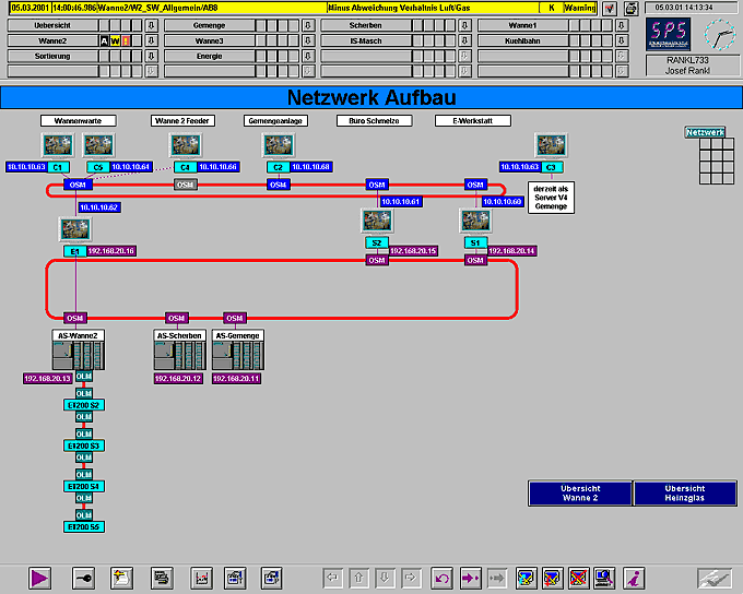
To prevent loss of data of the batch plant during the commissioning period, an old version 4 server was temporarily used as an „emergency operator panel“. While upgrading to version 5.1, this server was installed as a client, and process controlling was assigned to server 2. During commissioning, the engineering station was positioned on site (in the control room next to the tank). Normally, it is located in the electric shop floor for system maintenance and immediate troubleshooting.
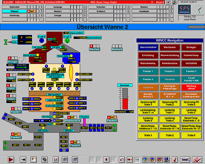
The picture below gives a quick general view of the regenerative 65 t tank including an additional electric heating from Glashüttentechnik Grob GmbH & Co. KG. To date, the melter runs only with feeders 2, 3 and 4. Feeder 1 will be put into operation some time later.
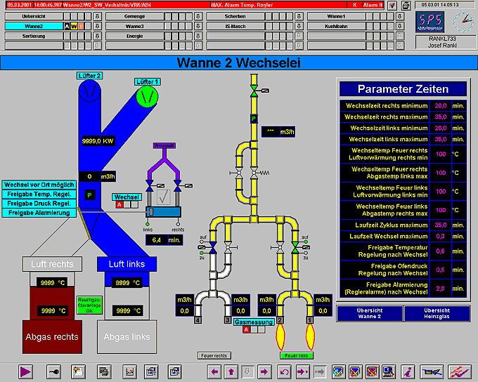
The fire is always turned on mutually left and right, because this is a regeneratively fueled end-fired melter. To provide equally high air pre-heating on both sides, alternation is no longer determined by time interval alone, but by various factors. Alternation itself is also governed by the AS416 PCS7 station, leaving only safety-related components (gas valves) subject to hardware controlling.
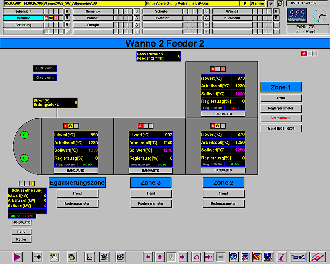
All the detail pictures provide quick information about the running process, as can be seen on the „Feeder“ picture. To achieve the desired accuracy, we programmed genuine tools for the controllers in use. The most important parameters (setpoint, actual value, working setpoint, control output) are displayed in the general view window. Extra functions such as cascading, thermocouple switches etc. are easy to handle in the control loop window, provided authorization for this domain is given.
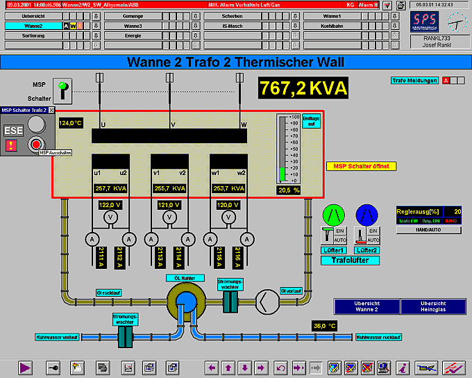
With transformer 2 for example, the operation of its plant components is also clearly possible. The essential cooling system as well as the fans and all transformer-related details are displayed and can be operated. Even the transformer output can be set in these windows.
The striking feature of using PCS7 in process automation is a general view of the entire process at any time. The user will never find the whole plant out of sight while navigating through different sections. A new report is always displayed in the top report bar. Additionally, the respective collective display is activated, indicating the new report by a flashing light. The following cases are can occur:
A = alarm (low- or high-alarm)
W= warning (e. g. tolerance)
! = unit controlling and manual operation
S = OS control system report